
Back in February this year (2013) I got a request from someone if I could repair a CR-78 with severe battery leakage. A repair-shop that was asked about it wouldn't do it because it would take too long and not be worth the time/money.
Well... I'm cheap, but I leave no guarantees that I'll fix it 100% or that I'll do it quickly, but I'll do my best. That was good enough for this guy, so he let me have a go at it.
The actual "practical" symptoms weren't actually that bad though: Not possible to save rhythms
No way should anybody give up on a such a fine machine unless it's totally hopeless.
Challenge accepted!
Evaluating the damage
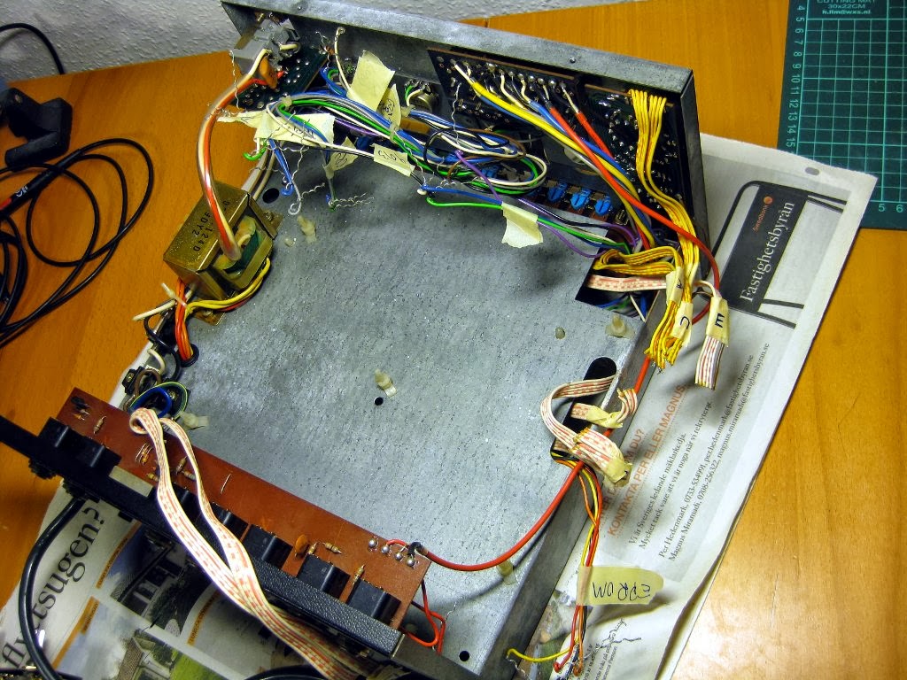
When opening it up and inspecting the PCB, I wasn't sure what to expect. (All images are clickable)

Looking closer at the logic PCB I saw very badly corroded traces and components. Here are some of the worst parts I could see.
| The instrument trigger transistors that sit next to the battery |
 |
| Diodes for the instrument selector switch |
 |
| EPROM and RAM sockets+chips with decoupling capacitors. Battery pad bottom left. |
 |
| Opposite edge of the PCB! |
What do you do when you see this? Just clean it off? No.
There was only one right thing to do:
Remove everything in the affected area, clean the PCB properly and replace ALL the components in that area with new ones, except parts that are extremely hard to find replacements for.
More bad news
I was informed that the owner was told to put bicarbonate on the area where the battery had been, to neutralize the battery acid, because bicarbonate is a base. When I first opened the unit up, I had to clean that off. If anyone reads this, please make note:NICKEL CADMIUM CELLS ARE NOT ACIDIC! THEY HAVE AN ALKALINE ELECTROLYTE!
When people think of battery electrolyte they probably think of car batteries (i.e. lead and hydrochloric acid). NiCad batteries are not constructed the same way. The electrolyte is Potassium hydroxide, commonly called caustic potash, and it's an alkaline/base, so you can't neutralize it with another base.
It doesn't help. If anything, you're pouring more gas on the fire by doing it.
But, since it's just a dry powder, it's really not such a big deal and I am pretty sure it had zero effect during the time it had been left there before I got it.
If you want to remove alkaline electrolyte leaks, I would suggest using either just water to wash it off, or something mildly acidic first, and then water, and finally alcohol. Make sure you dry it properly!
At least, that is my opinion. Correct me if I'm wrong...
Anyway, it wasn't really bad news, just a misconception that deserves some attention.
The really bad news is this:
The battery in the older versions (serial numbers up to 862899) used a 5.6V 4N-100AA NiCad battery. The "newer" ones (serials 872900 and up) used a lower voltage 3.6V N-SB3 NiCad battery.Here is a quote from the service manual under the comment about the 5.6V battery:
- D109 is removed at the factory to increase the charging current. However, there are some products having D109 on the market. REMOVE D109 on the first ocassion.
- (after D109 removed) Never turn on the power switch with 4N-100AA DISCONNECTED. HIGHER voltage will ruin IC102 and IC103.
Why am I telling you this? ... You guessed it.
This unit had a serial number lower than 872900.
D109 was missing.
The battery was removed.
The machine was tested after the battery had been removed.
I don't blame him for it though. It's a stupid design. Unless you read that very page in the service manual you have no idea about this problem and I don't think anybody expects it. I sure haven't seen it in any other machines and I didn't know about it until I read it myself.
The RAM isn't just any standard RAM either. It's a staggering 1024 BIT (256x4) SRAM, 22-pin, 400mil/0.4" pitch (!) chip.
Luckily I located some on eBay and ordered 2 before testing, as I assumed they were toast.
I already blogged about the battery replacement procedure separately. If you're only interested in that, you can read about it here: http://synthpeter.blogspot.se/2013/07/roland-cr-78-non-rechargeable-lithum.html
Finally, a major annoyance was that there were a lot of ribbon cables coming from the front panel and the analog board, and they were soldered, and then glued, directly to the logic board.
 |
| I'll just remove these and solder them back temporarily when I want to test it... I don't think so! |
There were more than those, but that was the messiest area on the board.
I guess they never expected anyone to ever want to service these things. If I was going to be able to test this, I had to put connectors for every ribbon cable.
Removing everything
It was time. I started labeling the ribbon cables and took photos so I knew where and how they had been attached. I took photos of every small group of wires, resistors, capacitors, diodes, ICs and sockets, documenting their position, orientation, designation and value.I can write pages and pages about this, but I'll just put a lot of commented random photos from the disassembly process here for your enjoyment :)

 |
| A RAM IC |

 |
| Label everything! |

 |
| Board removed! |
 |
| Here it is! Time to start removing components. |
 |
| You can see where the infamous D109 was located (betwen the diode and 120ohm resistor). |
 |
| Area where the battery and lots of ribbon cables were attached. |
 |
| Area where trigger transistors and resistors were. Nasty! |
 |
| The instrument selector diodes were here. |
 |
| RAM and EPROM sockets. Yes, these definitely have to go... |
 |
| ...and it looked like this below the EPROM socket... |
 |
| ...and like this under the RAM sockets. |
 |
| Most of the area under the CPU socket was also damaged. |
 |
| Some stuff near the opposite edge of the board from the battery. |
 |
| Document the value and orientation of everything. Also opposite end of the board. |
And finally...
 | |
| Everything I planned to remove is removed. Note I have already started rubbing some crust off near the battery. |
Cleaning time
Finally it was time to remove as much of the crust and as possible. I started by using a small hobby drill with polishing accessories, but it was very difficult to get it right, and if you touched some other part it had a tendency to just fly jump around and scratch everything. I also tried scratching some damaged pads and traces with an x-acto knife, but this was sooo slow and difficult.I wanted a better way to cover a large area quickly. I found a ball of old steel wool in my toolbox and tried it. Worked pretty well, but I wanted something even better.
After a while I came up with a more efficient way of doing it:
Sandpaper! :)
I never thought I'd use one on a PCB, but this one has really thick traces and there was a lot of crust and crud all over it, so I gave it a go. It actually worked surprisingly well! See for yourselves :)
 |
| The trigger transistors and resistors area. Much better! |
 |
| The EPROM socket pads. Quite an improvement! |
Aciiiiid! I mean.. Base!
This was the real mechanical removal process, but I was still worried there were electrolyte leftovers under components that I had chosen not to remove and in general all over the board. An acid would be a good way to neutralize any active remaining electrolyte and I read that vinegar might do the trick.So, I went and bought a bottle of 24% vinegar and basically wet the entire board (I didn't drown it completely, with switches and all, only the board itself and the component pins) and let it soak for a few minutes. Now I don't want to cause any damage, since acid does eat away on healthy metal as well. I just wanted a neutralizing effect on any remaining electrolyte, so I didn't leave it for too long.
After that, I washed it all off using regular tap water, which is almost neutral (at least compared to the vinegar and electrolyte). Finally, I gave it a good wash using a lot of isopropyl alcohol.
I did have to pay special attention to the pads the battery had been soldered to. They were blocked and full of hardened corroded solder. I applied the vinegar to the pads and let it react a bit. I actually saw bubbles forming in it! So yes, something was definitely happening there. After waiting for a few minutes I cleaned it off using water and isopropyl alcohol. I then re-heated the pads and applied new solder to them and used my solder sucker to remove it. The results were good and I was quite satisfied with the entire cleaning!
 |
| Minor accident in the bottom left corner. Trace ripped off when removing pins... No problems otherwise! :) |
I don't have a photo of it with just the spray coat applied, but you'll see what it looks like soon.
Rebuilding
Ordering parts
During my disassembly process I documented every part I removed and I had put an order from Mouser for most of the parts. I couldn't find any 1S1588 diodes (at least for any reasonable price IIRC), but after looking at the datasheet I was certain that a regular 1N4148 would be a perfect substitute.For the more exotic and obsolete stuff I had to order from eBay. For example the transistors were all 2SC1815GR and a few 2SA1015. These were most likely used just because they were cheap and common at the time and I could probably have replaced them using almost any generic NPN and PNP transistors. However, I played it safe and ordered some from eBay since they're a bit more of an active component than the diode and they were still easily obtainable and really cheap. I already talked about the RAM.
I got a nice surprise when I received what I had ordered from Mouser. The 40-pin socket for the CPU looked like this:
 |
| Look! It's a 38-pin socket! |
Populating the board
Again, there isn't much to say about the actual rebuilding process and I actually didn't take that many photos of it, but here are a couple: |
| New sockets for CPU, 2 logic ICs, RAM and EPROM. |
Note that in the picture above (and below) you can see a dark area.
That's where the protective spray coat was applied.
 |
| Trigger transistors area. Shiny new resistors! |
 |
| Molex connector crimping in progress! I actually had to buy the tool for it as I had never done this before. |
 |
| My first crimped connector! :) |
 |
| Headers for the ribbon cables around the battery area. |
 |
| Another header and some IC sockets. |
 |
| Meanwhile in the living room... |
Testing and repairing
When the board had everything put back I did the Lithium battery mod mentioned earlier, but I didn't mount the battery yet. The mod takes care of the problem with dangerous voltage to the RAM as well.I powered it up... Silence... Tempo LED stayed lit whatever I did.
Noooooooo! I broke it!!!
I started probing with the oscilloscope, looking for problems with triggers, clocks and whatever I could think of. It seemed like everything was working. Why was it silent??? But... I hear something very silent... ?
After a while I realized I had pressed all the "cancel voice" buttons and the volume sliders for all the "add voice" sounds were zero. I had also plugged the cable into the high-Z output, making whatever sound that was left almost impossible to hear... Idiot!!!!
I uncancelled the sounds and increased the "add voice" volumes. It worked!!! There was sound!!
Wooohooo! I didn't break it!
RAM and battery backup
I tested the machine with the old RAM chips first, and tried to record a pattern. Didn't work. The recorded pattern was just garbage and sounded like random triggers.I removed them and put the chips I got from eBay instead.
I used my bench power supply and a multimeter to check the expected battery current being drawn by the new RAM when the CR-78 was switched off. I found it to be 25nA, which is nice, but also an extremely unreliable value as it's almost the minimum value the meter could show. At least it showed that there was no short-circuit :)
I then tried to record a pattern. It worked! Yes!!!
I soldered the new Lithium battery to the board, recorded a pattern and then switched it off, waited a bit, switched it on again.
Pattern was gone. What?!
I made sure the mod I had done was correct. It was. Battery had 3.6V still. Were the chips broken anyway?
Hmm.. The memory didn't have any voltage on their VCC-pins...
It took me a while, but I found out the through-hole plating in the pads where the battery was soldered in was either damaged, or perhaps they were never through-plated to begin with. The traces that connected the battery to the RAM ran on the TOP side of the PCB and I of course had only applied solder to the bottom.
I applied some solder on the top side and tried again. Now the battery backup for the RAM worked fine! :)
Tempo LED
As I noticed when I thought the CR-78 was broken during my first test, the tempo LED wasn't blinking. Of course it turned out to be a wonderful coincidence. After some probing the the oscilloscope I could see that the flip-flop IC 115 (74C175 / CD40174, it had both numbers printed on it) that was responsible for controlling the LED did get the correct data, but didn't produce any output, so it was was broken. I replaced it and got the LED working again. Nice!Recording problem
The last problems I found was when I tested the recording function properly. I went through all the instruments and recorded them onto separate tracks as varied as I could.Now... Here's the problem with waiting too long with documenting what you have done...
I know that I had problems with recording all different instruments. I _think_ one problem was that some instruments just wouldn't get recorded. Again, I probed with the scope to find why it didn't work, all the way back to the RAM, via the CPU to the switch. After a while, I found I had an open circuit between an IC and a switch. This was definitely caused by the battery electrolyte corrosion.
 |
| See it? Second trace from the left, just a bit above where the 3rd trace begins. |
Once that was fixed, I still had problems with recording...
Some sounds were recorded as Low Conga instead of whatever they were supposed to be recorded as.
Now... I'm not sure which symptom was, since again, it was a few months ago, but after another lengthy analysis, I found that the instrument selector switch had two open circuits... Urgh!
So, I had to remove that horrible 11-position switch...
Here it is.

The switch looked like it was built from customizeable parts (note the black blind sheet at the rear) and should be possible to disassemble. Turns out it was quite easy if you just bent those four tabs on the front so they fit through the holes behind them.
Here's the selector partially disassembled.

The plate behind it though... There was supposed to be open circuits on that one and judging by all the blackened traces and the miscolourations, it's probably also damaged by corrosion.
Looking at the middle switching plate after it's been removed, it's obvious...

I tried to find where the open circuit was. I expected it to be between the contact tabs and the rotor tab, but surprisingly, the problem was at the riveted joint between the trace and the contact tab.
Look at it from the side...

It appears that the potassium hydroxide gas had found its way in BETWEEN the trace and the contact tab, causing open circuit at the rivets.
I gave the switch plate a nice treatment with vinegar and alcohol (sounds like a bad party) and without doing anything with the actual problematic rivet joints, the open circuit was fixed!

Looks a LOT better now as well, don't you think?
But, since the connection might go bad again at the problematic joints I decided to solder it together, just as an extra precaution.

Short pieces of resistor legs, soldered in place, were used to bridge the connection once and for all.
I put the selector back together, soldered it back onto the PCB and tested recording, and everything was working perfectly!
Actually, the start/stop button was not 100% reliable, but I sort of gave up on that. I don't think it can be opened and I doubt I'd be able to find a replacement. In any case, I had had enough of this machine now and I was just happy that it actually worked and the electrolyte was cleaned off!
New power plug
The last thing I did was to replace the weird old (danish?) un-grounded wall plug that was attached to the mains cable. The cable DID have a ground wire that was attached to the case in the CR-78, but the plug didn't have any ground. Hardy a legal job I'd say, but I guess whoever didn't couldn't care less...There's no photo of it unfortunately, but if you're desperate to know what it looks like you can see a part of it in the hi-res photo at the bottom, in the top left corner ;)
Done!
To round this massive post off, I'll add some more photos of the CR-78 after assembly.Note that you can see IC 115 (the flip flop I had to replace to get the tempo LED working).
Next to the trigger transistors in the center of the board, there are 4 ICs.
One of them is socketed. That's the one...


And finally, a shot of the entire board from above, with the masking tape removed from the ribbon cables ;)
(I almost forgot to do that before I gave it back to the owner)

The entire repair took about 3 months.
(2013-02-11 - 2013-05-27), though a lot of the time I was just waiting for components to be delivered.
Also, I realize I've just spent 6 hours writing this blog entry... :-/
This comment has been removed by a blog administrator.
ReplyDeleteHey Bruce,
ReplyDeleteWhew! That's love. Where are you? My CR is now on its third trip back to the Roland authorized shop in Van Nuys. I've never met a less curious guy than the one who didn't fix it the first time. My machine has a ghost that only lets it work properly when it's sitting on their bench.
~ Blacky
Your're my man! >3 Great work on such a great toy. Respect!
ReplyDeleteJayDee
I got a couple of them in the same state. Eventually I will strip one down one of the mother boards so I can scan it into the computer. Then I can make a copy of the traces so I can make new circuit boards.
ReplyDeleteGreat work. I bet most CR-78's get destroyed by battery leakage. The main board isn't very complicated and it's probably worthwhile to do a small run of boards. I've got 2 with the same problem. Redoing dozens of traces with wire is taking lots of time and it's very easy to miss a few broken circuits.
ReplyDeletehere's a NOS CR-78 board! Very rare
ReplyDeletehttp://www.ebay.com/itm/Roland-CR-78-Logic-Board-GL-9B-New-Old-Stock-/201448502973?hash=item2ee74436bd:g:WM4AAOSwo6lWHZct
Do you have closeup photos of all the wire-wrapped connections to the logic board? I have a CR-78 on the bench right now that also had a battery leak. The owner took it to a "tech" who removed the logic board, did some cleaning, and reinstalled it very sloppily. It never worked after that. Due to the quality of hte work ,I have no faith that he put all the wires back in the right places, so before I plug it in, I would REALLY like to know that the wires are in the right places.
ReplyDeleteThanks!
Dave Hamara (ishkabbible at gmail dot com)
Hi,
DeleteI'm not sure I have any good photos of all the wire connections.
Since it's not my unit I'll just have to take a look in my saved photos. I'll email you.
Dave Hamara, if you still need pics of the CR78 logic board I may be able to help you out. I just stripped mine and I am in the process of redrawing the board in Eagle cad so I can Have a new one made. Before I striped it I took hundreds of pics.
Deletedemoninstudio, are you still in the process of getting new CR78 boards made? Perhaps a number of us could do a group buy and donate some money to you for the redrawing work...
ReplyDeleteRobert, I have the CR78 board approximately 60%-70% drawn in Eagle Cad. It is very time consuming work and I shelved it for now. I still really want to get this done. If anyone out there has experience with Eagle Cad I will gladly share my files and make this a team effort. I also have an extensive collection of High Res pics of the board as well as the original schematics. I also was able to X-ray the board with the components removed. The X-ray shows all the traces in amazing detail. If I can't find help I will continue to plug away>
DeleteI'm not Eagle savvy but I know a few people to ask. I'm curious as to how you got the X-rays of the boards -- are they plain film, framelocked fluro, or digital CR? With careful selection of KV/mA or post-processing contrast you should be able to tease out two different intensities for the top and bottom layers and use those to generate the CAD files. Scaling shouldn't be an issue, either.
DeleteJames has passed the CR-78 torch to me with his two battery damaged units (Hi James!). Hoping to get at least one machine working but it's great having a second one to compare. I've noticed a few GL-9B logic board differences from Peter's pictures that aren't mentioned in the service manual:
*Diode 137 is missing. (this is connected to pin 3 of IC113, a TL075)
*Transistor Q13 has a 100 Ohm resistor between the Base and the Emitter (Emitter goes to GND)
*Diode 221 and R237 are position swapped on the board (5V part of the battery charge circuit)
Both of these units have these differences, are close in serial number and were built in the same month (date code prefix of '84' which in RolandSpeak is July 1979). Both of these units were built after the last service manual revision (which is ironically date June 1979). As far as I know there's no later service manual.
I'm also experimenting with replacing the 5101 CMOS RAM with an easier to soruce NVRAM with an adaptor (mostly used for pinball and coin-op video games). I'll let everyone know if I've been successful in completely eliminating the CR-78 battery problem for good.
Robert, not sure if it will let you see this but her is a link to the x-rays I took of the CR-78 main board. I understand what you are saying about post-processing to separate the top and bottom layers but I don't have the software to do it. My goal was to use this to help draw the board in Eagle and have a new one made.
Deletehttps://1drv.ms/f/s!AoakMCa316stdPN6DghJPdSjE9Q
Very nice X-rays, this saves a lot of work, will take a good look at it, is noticed the second layer is slightly less grey
DeleteI have a CR-78 which is working for the most part, all the preset patterns play various faders functioning but memorizing patterns doesn’t seem to work properly. It could be my user error but I did follow the instructions and watched videos. I’d like to rule out user error 1st, so if there are any CR-78 owners or programmers willing to assist I am happy to compensate for time. Contact me if interested at bpowers@pmtv.com or via facebook Brian Powers
ReplyDelete** I am a drummer in a genesis tribute band I would like to use the Roland live on stage.
mine has a similar problem - memorizing results in horrble glitchyness and repeating beats - my assumption has been that the RAM chips went bad, and I ordered some from ebay - both NOS and some designed for a Bally pinball machine - there was a rumor floating around that those were the same but better - however never had the guts to go in and start snipping the IC leads so i could put in some sockets... wish the guy who wrote this blog post could comment...
DeleteThis comment has been removed by the author.
DeleteAs luck would have it I ended up finding a working CR-78 that amazingly had an intact original battery that had not leaked in the intervening 40 years. Snipped that sucker ASAP, wrapped it in plastic and relocated it to the back of the CR-78 case in an area where it will do no damage if it does eventually leak.
DeleteMeanwhile it's working fine until I can come up with a better solution for the battery issue. I'm not a fan of replacing old NiCd for new NiCd because you are setting yourself up for the same type of leakage problems a few years down the line. I have in the past used NiMH battery stacks for cordless phones as NiCd replacements (in a CSQ-600) but you can run into other issues such as battery outgassing and the limited number of charges for NiMH before it fails. Isolating the charge circuit and using a CR2032 coin cell is possible but I'm also not a fan of this as they tend to have lower mAH and you'll be replacing them possibly every six months depending on how power hungry the RAM is -- not to mention that you will lose your drum patterns in the process unless you keep the machine powered (and do you *really* want to be messing around like that?). One option is a CR2032 paired with a supercapacitor to keep the RAM powered long enough to do the battery swap.
While I had the NiCd battery out I tested the NV 5101 replacement pinball RAM (and isolated it from the battery power feed). They weren't working and I end up getting constant drum beats that's typical of corrupt RAM and the memory erase function of the CR-78 didn't help. A couple of things could cause this:
1) The speed of the RAM may not be matched well and the CR-78 expects RAM slower than what can be sourced nowadays (though I believe I did buy the correct variant that should work in this situation)
2) The RAM is working but the CR-78's erase circuit doesn't properly clear it. The CR-78 is reading *something* off the RAM as far as I can tell. One way to check might be to use another working device that uses 5101 RAM (such as a pinball machine) and erase the RAM there and try again. If it works then it might be that the RAM needs to be 'initialized' in a certain way before it can be used in the CR-78. It might mean we have to modify the CR-78 memory erase circuit as well. I'll do so more research on the differences between the volatile and non-volatile versions of the RAM.
3) The NV RAM is fried because I was testing it in the other CR-78's and damaged it. Entirely possible but this should be easy to check in an appropriate pinball machine.
I'll update if I have any breakthroughs.
Anyone knows if the CR-78 motherboard project is still going on ?, am very eager amd whish to have one created/printed can donate and help out where I can
ReplyDeleteKevin, I took the x-rays. I made an attempt at drawing the board using my board as a reference but my knowledge of Eagle cadsoft is just not that good. My plan was to Draw the board and have a new one made. I also looked into possibly just sending my un-populated board out and have is scanned and reproduced. I have all the components to repopulate the board, but unfortunately havent had any luck getting it done. These machines are soo cool and there are many that have fallen victem to the leaky battery. You would thing there would be a calling for replacement mainboards. I'm willing to lend my rescources to anyone that wants to take this on.
Delete@demoninstudio - I'm willing to give it a shot, if you'd like to share :) I've two dead CR-78s here with the usual acid problems, and have had some past experience with Eagle. If anyone's interested, I'd do a run of maybe 10 boards, if folks want to chip in. I just want these two machines back from the dead :)
Deleteemail: cooties at mac dot c o m
Alison, if your still interested I can upload all of my scans and pics to an online drive and give you access to all of the data I have collected. I keep looking at my non functioning CR78 and its a real bummer......
Delete@demoninstudio Aside from the x-rays that you've provided here (thank you, by the way!) do you have any other hi-res images of both sides of the main board? I started a project a while back where I was just tracing over the x-rays in Adobe Illustrator but I think I eventually stopped because it was difficult at times to sort out what was what. Is there any more movement on this from any of the other commenters here? I am also in the same boat with a well-corroded CR that I'd love to see working again. Let me know! Thanks!
Delete–Jeff
Jeff, have you checked out the CR-78 service manual? There's drawings showing the placement and orientation of the components on the boards and it also shows the etch mask -- or at least the topside mask, which might make it easier to determine what's part of the underside by process of elimination.
DeleteA long term project I've considered is to make a drop-in upgrade for the 8048 that has it's own flash RAM. A few things I would like to add would be expanded user memory (in banks, selected by button combination or by making every button user programmable), the possibility to combine more than two patterns at a time and/or the ability for two simultaneous patterns to have different clock divisions, and user programmable fills simultaneous with A/B pattern selection.
Jeff, here is a link to all of the pics I took. In this folder there are 2 pdf. files that are scans of the board I x-rayed. Glad to here someone is still interested. I would really like to get mine back into operating order. Please let me know if I can help in any way.
Deletehttps://1drv.ms/f/s!AoakMCa316stgQAqXxDUr-DWO8eF
https://1drv.ms/f/s!AoakMCa316stgQAqXxDUr-DWO8eF
Delete@Robert yes I have - in my AI file I have the service manual scans next to the xrays i'm tracing but it's still slow going. I'll have to dive back into it.
Delete@dmoninstudio these files are great and super helpful! thank you for sharing this!
Hi, thanks for your reply, love the work you did !!! would it be an option to make a photocopy of your board on transparant plastic (both sides), then use that to UV light an PCB, and then etch it ?
ReplyDeleteFriendly greetings, Kevin
Update!... I contacted a company that scans pcb boards and transfers them to gerber files for production. I sent them pictures and xrays of my board and they were willing to take on the project however because of the damage to my board it is pretty extensive and the quote I got from them is $3800.00. This is out of my price range. I still think someone with CAD design knowledge could re draw the board and make this happen. Wish I had that skill because there seems to be a market for this.. :(
ReplyDeleteI'm about to embark on one of these - the one i'm working on is from May of 1979 and has the newer board with molex connectors. But I had to desolder and wriggle out all the wire-wrap posts! God what a pain that was. Labeled everything, obviously. But check this out: https://www.flickr.com/photos/10000341@N05/49144792137/in/dateposted-public/
ReplyDeleteIn the pic, this is the bottom of the board, and you can see the molex connectors at the ground zero damage area have been wired underneath to the destination, I'm guessing in an attempt to bypass the damaged traces? Can you shed any light on this? I'm pretty sure this isn't factory... did your board look like this underneath? I'd like to actually fix the corrosion problem. The battery had already been replaced with a 3.6v and the diodes cut.
Hi. Yeah the wrapped wires were a pain. Sometimes I worry if I wrapped them tightly enough when reassembling it...
DeleteThe cut diodes look the the correct ones to cut if replacing the battery with a non-rechargeable type.
Your board looks like it could use some cleanup, yes. You noticed the area around the diodes by the instrument selector and under the molex headers. I'd remove those and clean that up.
The wires on the bottom look a bit chaotic, but I guess if you just check for continuity between the supposed points they're supposed to connect and it looks good, then I guess it's fine.
You do have some really sad looking traces on the top side by that row of transistors and resistors near the original battery terminal pad. This is not a factory mod, especially considering the battery is also replaced with a lithium cell. I can't tell if the fix is working or not, but again, a proper cleanup and double checking of the existing repairs should hopefully be enough.
If you want to be extra careful, remove the RAM ICs (or anything socketed) carefully, before probing and testing, so you can check the voltages at the IC supply pins.
Other than that I can just say good luck :)
Just to reinforce Peter's comments, I would try to clean up and neutralize as much of the corrosion as possible. The leaking from NiCd batteries is alkaline in pH, turning the elemental copper and aluminum into their oxide forms and continues to create an alkaline environment which will creep along traces and continue to damage things for years afterward. This kind of insidious battery damage is the bane of my existence!
DeleteThank you both - actually the reason I'm repairing is because i noticed that the rock preset didn't work, and then gradually other things started going weird on it, but it's been so long that I don't even remember what it was. I pulled it apart a couple years ago and we noticed the corrosion, and I had read this blog post around the same time so I knew that I was likely going to have trouble going forward unless I fixed the root of the problem.
DeleteBut regarding the wires on the bottom of the board, should I leave them be? Was this definitely an attempt to bypass the faulty traces you think?
Definitely a trace repair. I checked a couple of them and they match the traces in the service manual. That loose red wire should go between where all the others are attached (on the IC pins). There's a pin that has none and it looks as if it's just come loose from there.
DeleteIt's like oxoxxxoo, where x=wire, o=just pin. The loose red wire should be soldered to the o between the x:es , if that makes sense :)
That's what I was thinking. I did see that there was one broken so who knows if that caused the other issues. In theory I should be able to remove them after repairing the traces, yes?
DeleteIn theory yes ;) Repairing traces can be difficult if they're corroded in several places or there are long stretches of trace damage. It's common to repair bad traces by running a wire instead. However smaller wire is usuall used, like wire-wrap AWG 28 wire or something. Usually the wires are run closer to the board as well and if they're long, held in place with a bit of tape or similar. Not like those big airborne ones. But at the end of the day, as long as it works and lasts it's probably ok.
DeleteWell looks like the repair was a success, I was able to remove those wires from the bottom, repair the traces, and what wasn't working is seemingly working now. I also re-capped both boards while I had it open. Hey, maybe the programmer actually works now...
ReplyDeleteI guess everything works with the exception of the FoxTrot preset... I thought it was working but I had a rhythm from the top section playing still.. doh. Back to the service manual! Everything works but that one selection...
Hello everyone !
ReplyDeleteI have built a new logic board (this is an exact clone of the GL-9 logic board) as mine was totally destroyed and couldnt do anything from it ..
So I decided to draw it on Kicad and here it is, a brand new board fully working !
If you are looking for a real solution for your CR-78 you can contact me as I have so spare boards.
@Safari, that's awesome! I definitely need a clone board (or two) as I have a couple of parts CR-78s that are hopelessly battery damaged. Is there an easy way to contact you? I can't seem to do it through the Blogger interface (and it's not displaying your email address).
DeleteI am very interested in one of these boards as well. I did a bunch of work trying to redraw mine but was unable to finish. Please let me know if it’s possible to get one, I’d be incredibly greatful. demoninstudio
Deletedmonfette2013@charter.net
@Safari, I am very interested in either a PCB or the KiCad files, please email me at telefunkian at proton mail.com
DeleteThanks for sharing, great work, you've been very helpful. Cheers Matt
ReplyDelete